
Pump coupling alignment is essential for maintaining system reliability, especially in ANSI metallic and non-metallic pumps used across chemical processing, effluent treatment, and water purification. These pumps handle corrosive and abrasive fluids but are structurally sensitive. Even slight misalignment can stress housings, seals, and bearings.
In industries governed by standards like CPCB and ISO 9906, misalignment leads to equipment failure, compliance risks, and higher maintenance costs.
Knowing how to check pump coupling alignment helps reduce vibration, extend seal life, and improve system efficiency. It supports preventive maintenance and energy-saving goals. Proper alignment techniques also minimize unplanned downtime in continuous operations.
Key Takeaways:
- Understanding how to check pump coupling alignment is essential to reduce wear, prevent equipment failures, and ensure long-term reliability in industrial systems.
- The main types of misalignment are parallel, angular, and axial, each requiring precise measurements using dial indicators, feeler gauges, or laser alignment tools.
- Checking pump coupling alignment must include safety steps such as lockout/tagout and allowing equipment to cool before inspection or correction.
- Early signs of misalignment, including elevated pulsation, noise, or temperature near the coupling, allow for proactive maintenance and reduced downtime.
- Practicing how to check pump coupling alignment contributes to lower energy use, improved equipment life, and reliable operations in industries such as sugar, chemical, and water treatment.
To begin, it’s important to examine the basic role of coupling alignment and how it influences the operation of rotating equipment.
Understanding Principles of Effective Pump Coupling Alignment
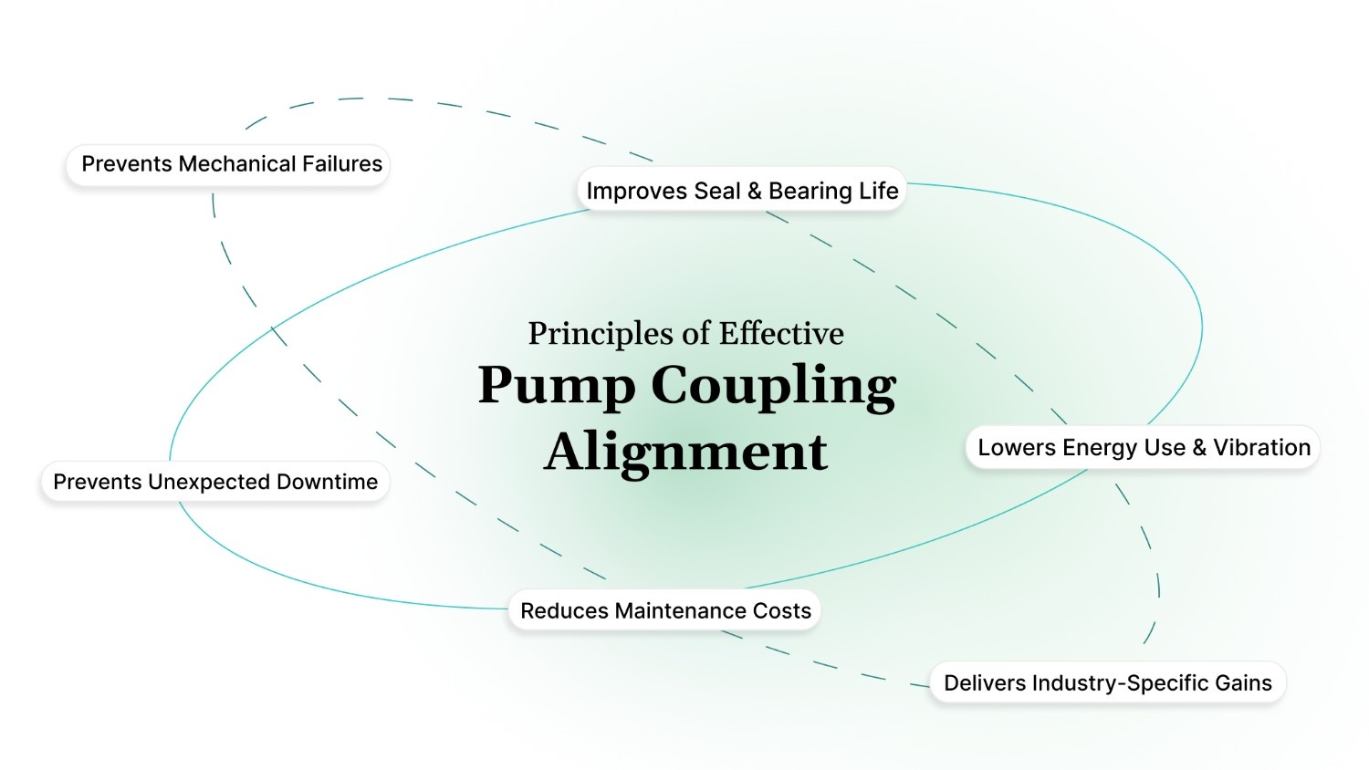
To appreciate why precision matters so much in pump maintenance, it's important to understand the fundamental purpose that proper alignment serves in industrial systems.
- Prevents Mechanical Failures: Misalignment over 0.05 mm reduces bearing life by 50%, causes shaft fatigue, seal distortion, overheating, and instability above 3000 RPM.
- Improves Seal and Bearing Life: Precision alignment (within ±1 mil, ISO 1940 limits) keeps seal runout within 0.002 in TIR, extending seal life 2–3x and bearing life to 18+ months.
- Lowers Energy Use and Vibration: Proper alignment reduces power consumption by 5–10% per pump and keeps vibration within ISO 10816 limits, critical in hygiene-sensitive industries.
- Prevents Unexpected Downtime: Misalignment leads to premature wear, shaft cracks, and coupling damage, increasing the risk of unscheduled shutdowns and costly emergency repairs.
- Reduces Maintenance Costs: Regular alignment during installation or maintenance avoids frequent seal and bearing replacements, cutting repair frequency and downtime.
- Delivers Industry-Specific Gains: Avoids shaft deflection in sugar pumps, maintains precision in chemical/pharma systems, and ensures high-speed stability in food and textile plants.
Before selecting tools or alignment techniques, it's essential to identify the specific type of misalignment affecting your system, as each form impacts performance differently.
Types of Coupling Misalignment
To understand how to check pump coupling alignment effectively in horizontal centrifugal pumps, including metallic and non-metallic types, it's important to identify the three main types of misalignment.
Each affects performance differently and can impact system reliability. Using the correct tools to detect and correct them ensures efficient power transfer and reduces downtime.
The table below outlines each type of misalignment along with key specifications, tolerance values, and commonly used measurement tools.
Once the importance of alignment and its types is understood, the alignment procedure can begin.
How to Check Pump Coupling Alignment: Practical Steps
Accurate alignment helps reduce energy consumption by up to 10%, extends seal and bearing life by over two times, and significantly cuts down on unplanned maintenance.
Knowing how to check pump coupling alignment with proper tools and techniques ensures reliability, improves uptime, and strengthens your return on maintenance investments.
Follow the procedure below to perform an accurate coupling alignment based on the tools and techniques used in industrial pump setups.
Step 1: Perform Rough Alignment (Preliminary Check)
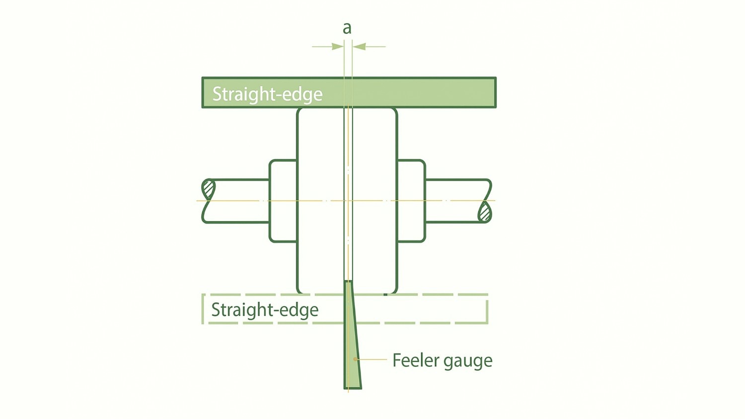
Start with a basic check before moving to precision alignment tools.
- Place a straightedge across the coupling hubs to check for parallel misalignment.
- If light passes unevenly under the straightedge, the alignment may be incorrect.
- Use feeler gauges to measure the gap between coupling faces at 0°, 90°, 180°, and 270°.
- Ensure the variation is within the manufacturer’s limit—typically less than 0.002 inches (0.05 mm) for soft-coupled systems.
Step 2: Use Dial Indicators for Angular and Offset Alignment
Dial indicators help detect both angular and parallel misalignment with high precision.
Angular Alignment Check:
- Mount the dial indicator base on one coupling hub and place the plunger on the other. Rotate both shafts together and record readings at 0°, 90°, 180°, and 270°.
- A difference in readings between the 0° and 180° positions indicates angular misalignment.
- The acceptable tolerance is generally less than 0.001 inch per inch of coupling diameter.
Parallel (Offset) Alignment Check:
- Mount the dial indicator based on the pump shaft and place the plunger against the motor shaft, or vice versa.
- Rotate both shafts and take readings at the same four positions. Any variation in readings indicates offset misalignment.
- Correct this by adjusting the motor position using shims vertically or sliding the motor horizontally.
Step 3: Use a Laser Alignment Tool for Accurate Measurement
Laser alignment tools provide a quick and repeatable way to achieve precise coupling alignment.
Attach laser heads to both shafts and input shaft diameter, coupling length, and other required dimensions into the device. Rotate the shafts as instructed, usually at 9, 12, and 3 o’clock positions. The device will show real-time alignment status and suggest corrective actions.
Typical Alignment Tolerances (ISO 1940/1):
Adjust the motor position as per the tool’s guidance until the alignment values fall within acceptable limits.
Step 4: Check for Soft Foot Condition
Before performing the final bolt tightening, verify if all four motor feet are making even contact with the base.
Loosen each bolt and use feeler gauges at all feet. If any foot has a gap greater than 0.002 inches, insert the appropriate shim to eliminate the gap. A soft foot condition can distort shaft alignment even after precise adjustments, leading to future resonance issues.
Step 5: Final Checks and Documentation
Once the coupling alignment is confirmed:
- Rotate the shaft again and recheck readings to ensure consistency.
- Tighten all mounting bolts using a torque wrench set to the recommended value.
- Reinstall the coupling guard securely in place.
- Record final alignment details, including tool type, alignment readings, shim values, and any corrections made.
- Conduct a trial run to check for unusual noise, or temperature rise.
Once you understand the importance of alignment in maintaining performance, the next step is to choose the right tools for the job.
Essential Tools for Pump Coupling Alignment
Achieving precise coupling alignment relies on the right set of tools and techniques. These instruments help identify misalignment accurately, apply necessary corrections, and ensure consistent machine performance.
The table below outlines commonly used tools in pump alignment, along with their core functions, application methods, and key specifications.
Before proceeding with tool selection, a structured safety process must be followed to protect both equipment and personnel.
Pre-Alignment Safety Measures for Pump Systems
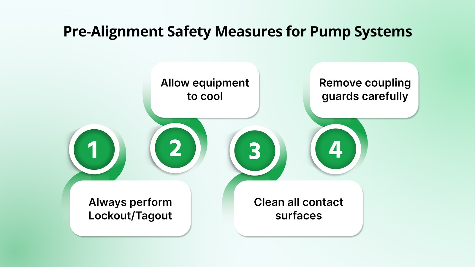
Before starting any alignment procedure, it is essential to follow a series of controlled safety steps. These actions help prevent equipment damage, protect personnel, and ensure the accuracy of the alignment process.
Skipping these precautions can lead to thermal distortion, incorrect readings, or accidental re-energization of rotating parts.
To support safe and reliable maintenance, here are the key steps to complete prior to alignment:
- Always perform Lockout/Tagout (LOTO): Isolate all electrical and mechanical energy sources connected to the pump and motor. Use LOTO devices to prevent accidental startup.
Example: Before opening a coupling guard, tag out the motor starter at the control panel and secure the disconnect switch.
- Let equipment cool to ambient temperature: Hot pumps or motors can expand and distort shaft alignment. Wait until components are fully cooled.
Tip: Use an infrared thermometer to confirm surface temperature before starting alignment.
- Clean all contact surfaces: Dirt, rust, or oil on coupling faces or shafts can affect tool readings. Wipe all surfaces clean before setting up alignment tools.
Example: Use a lint-free cloth and degreaser to clean shaft ends before mounting dial indicators.
- Remove coupling guards without damaging components: Ensure full access to the coupling while preserving guard integrity for safe reassembly after alignment.
Tip: Label each guard and bolt during disassembly to make reinstallation faster and safer.
Before serious mechanical issues arise, misalignment often shows early warning signs. Here's what to watch out for.
What Are the Common Signs of Pump Coupling Misalignment?
Even well-built pumping systems in industrial environments can suffer from coupling misalignment over time. This is especially important for mid-to-large scale operations in sectors such as chemical processing, food and beverage, water treatment, and power generation, where consistent uptime and equipment reliability are critical.
In industries like pharmaceuticals, oil and gas, dairy, fertilizer, and pulp and paper, misalignment not only reduces operational efficiency but can also increase energy costs and risk of non-compliance. Below are the most common warning signs:
- Elevated Vibration at Coupling Frequency: Abnormal motion around the coupling area is a key indicator. In high-speed setups such as textile, cement, and metal plants, this often appears at specific frequencies and may strain connected components.
Best Practice: Use laser alignment tools with vibration tracking. Keep vibration levels under 2.8 mm/s RMS in high-RPM systems. Monitor changes during routine shutdowns and log them.
- Premature Bearing or Seal Failure: Misalignment places uneven pressure on seals and bearings, leading to leaks and wear. This is critical in food, pharma, agrochemical, and dairy, where hygiene and safety are non-negotiable.
Best Practice: Check seal and bearing conditions during preventive maintenance. Maintain shaft offset within ±0.05 mm. Realign after seal or bearing changes using dial gauges or laser tools.
- High Temperatures Around Bearing Housings: Friction from misalignment raises bearing temperatures, especially in thermal power, sugar, and chemical units, where ambient heat worsens the effect.
Best Practice: Use IR thermometers or thermal imaging to detect hotspots. Maintain alignment within 0.1 mil/inch angular tolerance for pumps running above 3000 RPM.
- Unusual Noise Near the Coupling: Grinding or rattling noises often point to shaft misalignment. In sectors like poultry, brewery, food, and chemical, this noise is a sign of stress on components.
Best Practice: Train operators to flag unusual sounds. Use ultrasonic detectors during inspections. Recheck coupling alignment monthly, especially in hygiene-sensitive plants.
- Shaft Cracks or Damaged Keys: Long-term misalignment leads to shaft fatigue or broken keys, common in fertilizer, dyes, cement, and pesticide plants, where load and cycle times are high.
Best Practice: Inspect shafts and keyways during overhauls. Keep alignment within ±1 mil offset and angular deviation under 0.05 mm per 100 mm flange diameter. Use flexible couplings where thermal growth is expected.
Noticed signs of misalignment? Chemitek ensures lasting pump reliability with precision-engineered designs and inbuilt alignment solutions tailored for demanding industrial operations.
Pump Coupling Alignment: Maximum Reliability with Chemitek
Proper pump coupling alignment reduces disturbance, lowers energy use, and extends the life of key components. Chemitek Process Equipments Pvt. Ltd. ensures alignment precision in every pump system to help sugar mills maintain consistent and efficient operations.
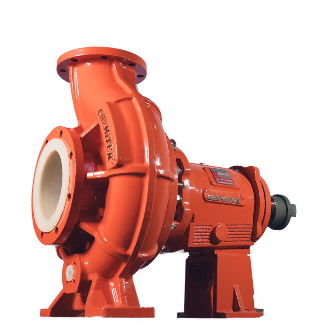
Built for durability and performance, Chemitek’s metallic and non-metallic centrifugal pumps rely on accurate alignment to prevent early wear on bearings, seals, and shafts while ensuring smooth function under the demanding conditions in industries such as sugar, chemical processing, and fertilizers.
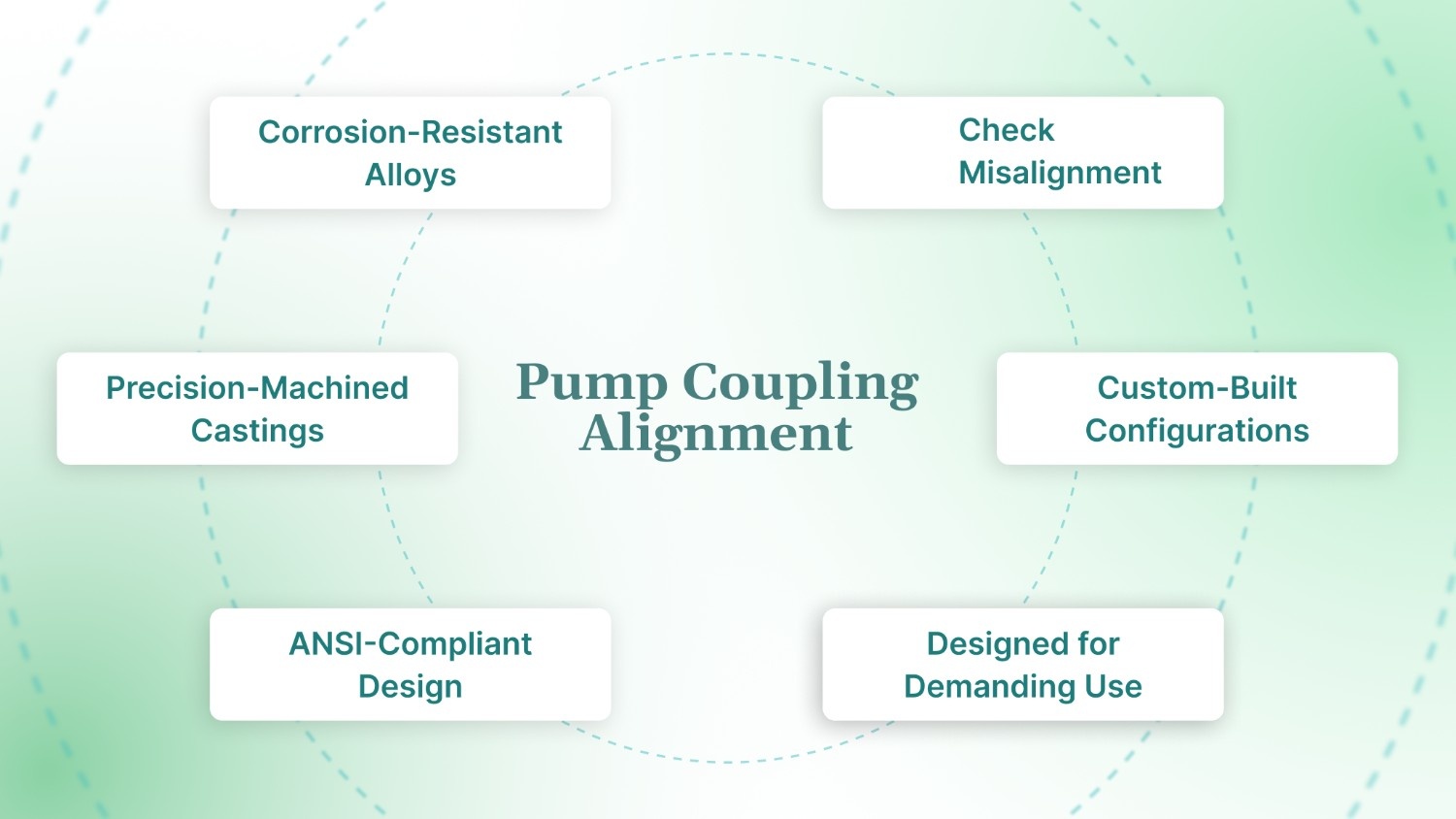
Here are key alignment-integrated design features in Chemitek pumps:
- Corrosion-Resistant Alloys: Built with SS316, SS316L, SS304, Hastelloy, and Alloy 20, Chemitek’s corrosion-resistant pumps withstand aggressive fluids and maintain long-term alignment in harsh environments including toxic fluid handling.
- Precision-Machined Castings: Investment-cast components improve hydraulic efficiency and minimize vibration, helping sustain alignment in high-pressure, high-flow applications.
- ANSI-Compliant Design: Built to ANSI/ASME B73.1 standards, these ANSI centrifugal pumps handle flows up to 1400 m³/hr and slurry concentrations up to 30%, ideal for chemical transfer and wastewater treatment.
- Operational Stability: Designed to handle thermal variations and fluctuating loads, these industrial pumps for oil & gas, fertilizers, and dairy plants maintain stable alignment across changing conditions.
- Custom-Built Configurations: As a custom process pump manufacturer, Chemitek designs pumps tailored to specific flow, head, and material requirements, ensuring alignment across diverse operating setups.
- Designed for Demanding Use: Especially suited for horizontal centrifugal pumps used in high flow, high temperature, or corrosive environments such as acid handling, pharma fluid transfer, and high-temperature process systems.
For reliable, energy-efficient pumping systems with built-in alignment precision, partner with Chemitek, one of the trusted centrifugal pump manufacturers in India and chemical pump suppliers to the USA.
Conclusion
Coupling alignment is essential for maintaining the efficiency and performance of centrifugal pumps in the sugar industry. Tools like dial indicators or laser systems ensure pump and driver shafts stay aligned within required tolerances.
A structured alignment process prevents mechanical failures, lowers excessive motion, and reduces unplanned downtime in centrifugal pumps. It improves reliability, extends pump life, and supports consistent performance during peak operations.
To cut maintenance costs and keep your operations running smoothly, make coupling alignment a routine part of your maintenance plan. Contact Chemitek to explore engineered pumping solutions built for long-term reliability.
FAQs
1. Why is soft foot correction important before aligning the pump and motor?
Soft foot occurs when one or more motor feet do not make proper contact with the baseplate. If uncorrected, it can distort alignment readings and introduce mechanical stress, increasing the risk of seal leaks, vibration, and premature equipment failure.
2. What benefits do laser alignment tools offer over dial indicators?
Laser alignment tools provide accurate, digital readings and guide technicians through precise shaft positioning in less time. They are ideal for high-speed or mission-critical systems where accurate alignment reduces wear and prevents unexpected downtime.
3. How does misalignment affect non-metallic centrifugal pumps?
Misalignment increases noise levels and uneven load on components like bearings and seals. For non-metallic pumps, this can lead to housing cracks, shaft damage, and more frequent replacements due to the material's limited tolerance for stress.
4. Can thermal expansion impact coupling alignment?
Yes, heat can cause components to expand, changing shaft positions. Alignment should be done cold, but thermal growth factors must be considered during setup, especially in systems with high operating temperatures.
5. Is it possible to align a pump without removing the coupling?
Yes, alignment is possible without full coupling removal if both shafts can rotate together. However, the coupling should be loosened to allow accurate measurement and adjustment during the alignment process.
6. How often should coupling alignment be checked in pump systems?
Alignment should be checked during installation, after maintenance activities, and at regular intervals based on usage. For continuous-duty industrial systems, inspections every 6 to 12 months are recommended to prevent alignment-related wear.
Latest posts
Ready to Upgrade Your Process Operations?