In industrial fluid handling, pump selection isn’t just about horsepower or flow rate; it’s about understanding how energy is transferred to the fluid and how that transfer behaves under process conditions.
Rotodynamic pumps, a category that includes centrifugal, axial, and mixed flow designs, operate on the principle of dynamic action: they impart kinetic energy to the fluid, which is then converted into pressure energy.
Unlike positive displacement pumps that move fixed volumes, rotodynamic pumps offer continuous flow and are favored for high-throughput applications with variable loads.
But not all rotodynamic pumps are created equal. Differences in flow direction, impeller design, and casing geometry can drastically impact efficiency, reliability, and suitability for corrosive or high-solids environments.
This guide breaks down what makes a pump “rotodynamic,” how it works, where it fits best and why the right component-level engineering is critical for long-term performance.
Key Takeaways
Rotodynamic pumps are defined not just by how they move fluid, but by how well internal components are specified for the operating environment. From impeller geometry to seal systems and materials, every element plays a role in uptime, safety, and cost.
- These pumps excel in continuous, high-throughput operations where flow conditions vary
- Performance depends on balancing hydraulic design with chemical, thermal, and mechanical stressors
- Material misfits or poor alignment can lead to cavitation, seal failure, and downtime
- Purpose-built designs offer greater reliability than generic configurations
In industries where unplanned shutdowns aren’t an option, design precision makes all the difference.
Understanding Rotodynamic Pumps
Before diving into types and applications, it’s essential to understand what defines a rotodynamic pump and how its core operating principles differ from other pumping technologies.
What Makes a Pump “Rotodynamic”?
The term rotodynamic refers to pumps that use rotating elements, typically impellers, to transfer energy to a fluid. Unlike displacement-based mechanisms that trap and push fluid in discrete volumes, rotodynamic pumps use dynamic movement to accelerate the fluid continuously.
The key feature: kinetic energy is added to the fluid via rotating impellers, which is then converted into pressure energy as the fluid exits through the casing or diffuser.
How It Works: Flow, Pressure, and Kinetic Energy
In a rotodynamic pump, the impeller rotates at high speed, drawing fluid into the center (eye) and accelerating it outward through centrifugal or axial force. This high-velocity fluid enters a volute or diffuser, where the velocity is converted into pressure.
The continuous flow nature of rotodynamic pumps makes them ideal for processes that require:
- Steady, non-pulsating delivery
- Scalability across wide flow ranges
- Low maintenance under varying load conditions
Rotodynamic vs. Positive Displacement Pumps
Each has its place. But for high-throughput, continuous-flow systems, especially where fluid properties change, rotodynamic pumps often offer better long-term efficiency and flexibility.
Types of Rotodynamic Pumps
Rotodynamic pumps are classified based on the direction of fluid flow through the impeller: radial, axial, or a combination of both. Each type serves distinct pressure and flow requirements, making selection critical to system performance.
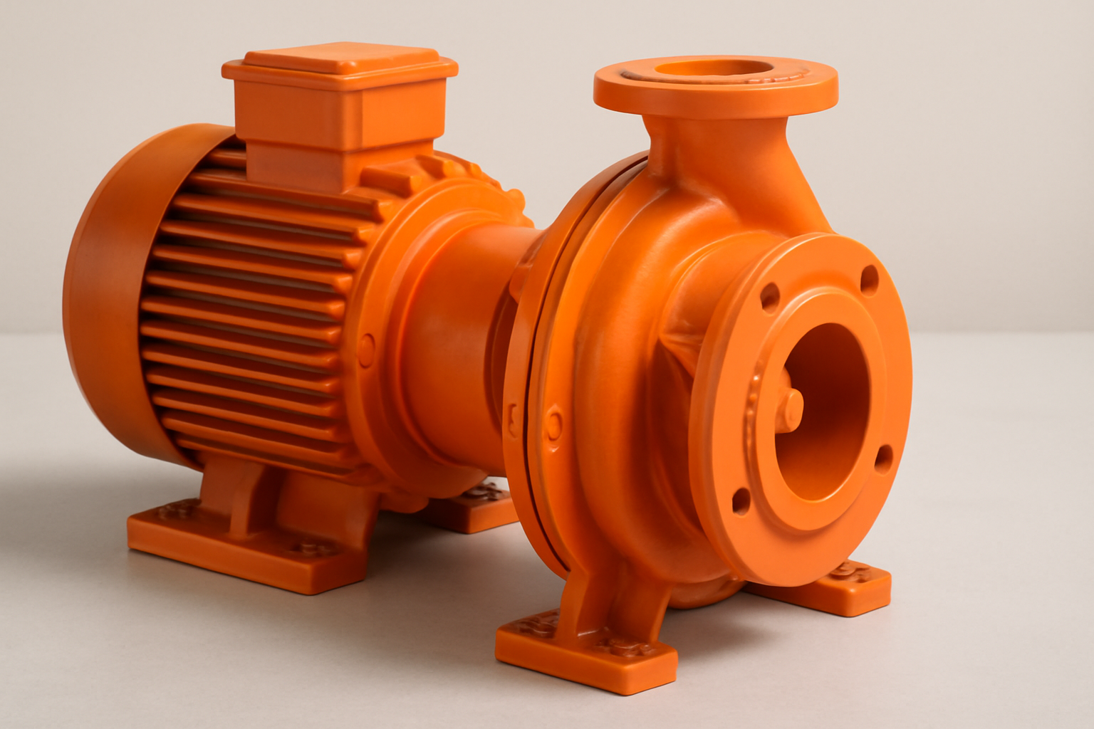
Radial Flow
Radial flow pumps are the most common type of rotodynamic pump and are typically used when high pressure and moderate flow rates are required. In this design, fluid enters the impeller axially (along the shaft) and is discharged radially perpendicular to the shaft, as centrifugal force accelerates the fluid outward.
Key Characteristics:
- High Head, Moderate Flow: Ideal for applications that need significant pressure without extremely high flow volumes.
- Compact Design: Often used in multistage configurations for very high-pressure systems.
- Applications: Chemical processing, boiler feed systems, high-pressure water supply, and reverse osmosis.
The impeller and volute geometry are engineered to convert high-velocity flow into pressure efficiently. However, radial flow designs may be more prone to vibration if not properly balanced or aligned.
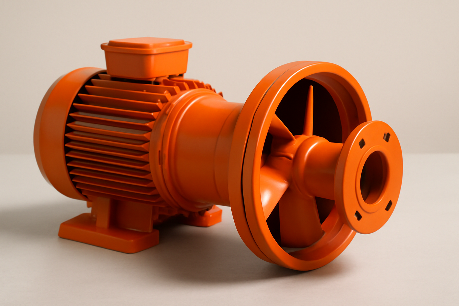
Axial Flow
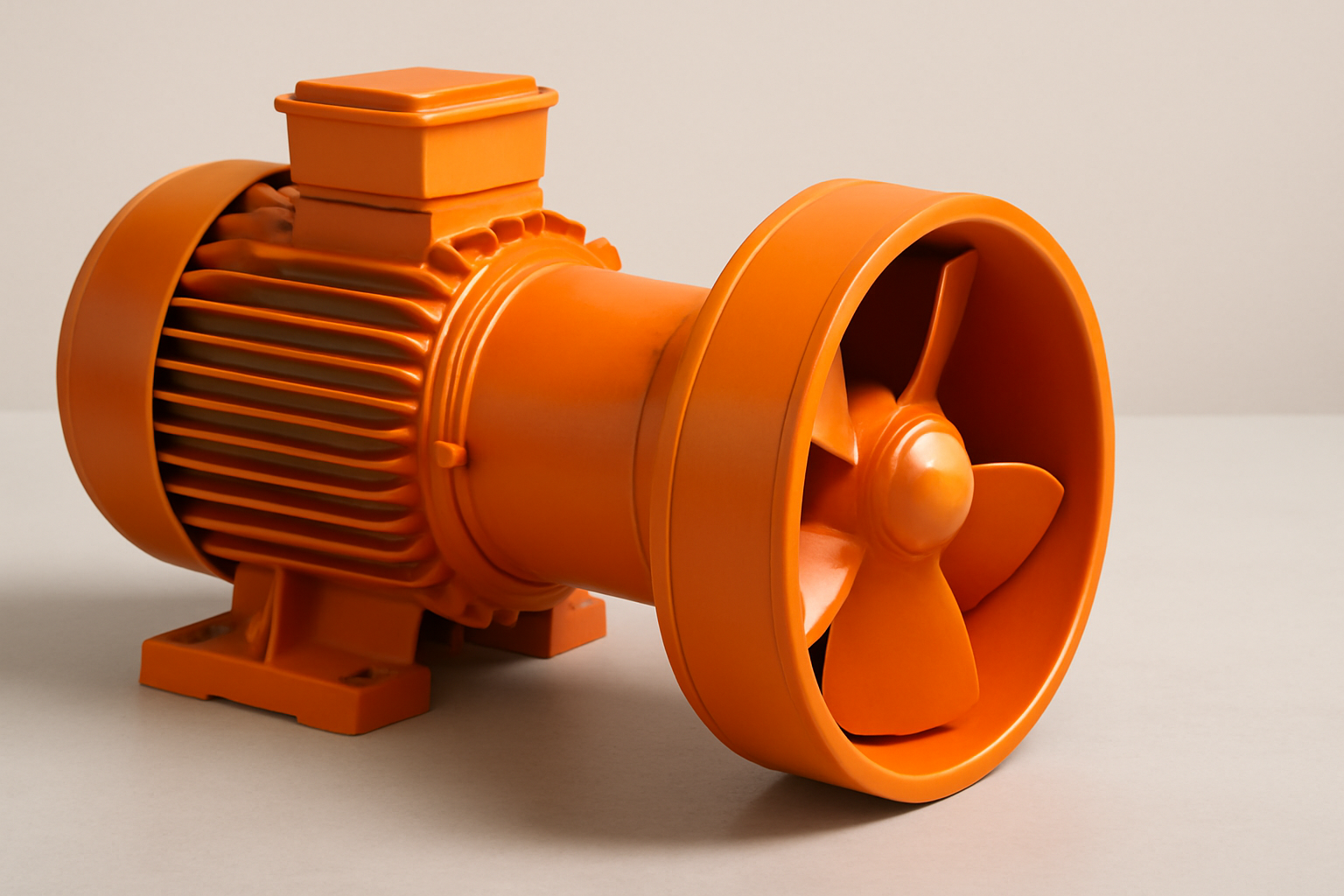
Axial flow pumps move fluid primarily along the same axis as the impeller shaft, similar to how a propeller works. Instead of generating high pressure, these pumps are designed to deliver exceptionally high flow rates at relatively low heads.
Key Characteristics:
- Low Head, High Flow: Ideal for transferring large volumes of liquid over short vertical distances.
- Propeller-Style Impellers: These produce lift, not centrifugal force, making the pump suitable for steady, streamlined flow.
- Applications: Flood control, circulation in cooling towers, water treatment, and irrigation systems.
Axial flow pumps are energy-efficient for continuous-duty, large-volume operations, but are not suitable for high-pressure or high-viscosity applications.
Mixed Flow
Mixed flow pumps combine characteristics of both radial and axial flow designs. Fluid enters axially but is discharged at an angle, creating both velocity and pressure through a hybrid impeller geometry.
Key Characteristics:
- Balanced Performance: Offers moderate head and flow rate ideal for applications that require both.
- Angled Impellers: These create a blend of axial lift and radial acceleration.
- Applications: Cooling water circulation, wastewater pumping, and certain chemical transfer processes where neither pure axial nor radial flow suffices.
Mixed flow pumps are versatile, making them suitable for variable-duty operations where system conditions fluctuate or require a balance between pressure and volume.
While radial, axial, and mixed flow classifications define the flow direction and pump geometry, they don’t always tell the full story, especially when it comes to real-world applications. This is where centrifugal pumps, the most widely used type of rotodynamic pump, come into sharper focus.
Where Centrifugal Pumps Fit In
Centrifugal pumps are the most widely used subset of rotodynamic pumps, and for good reason. They offer a versatile, efficient, and cost-effective solution for handling a broad range of fluids in both industrial and commercial settings.
What distinguishes centrifugal pumps is their radial flow design. As fluid enters axially and exits radially, it gains velocity from the rotating impeller and is then converted into pressure by the casing (volute or diffuser). This makes them ideal for medium- to high-flow, low-viscosity applications.
Common Use Cases:
- Chemical processing: For clean or slightly corrosive fluids
- Water supply and wastewater: Municipal or industrial
- HVAC systems: Circulation and cooling loops
- Food and pharma: With hygienic builds and seal systems
Why They’re So Common:
- Simple construction and maintenance
- Wide availability of materials (metallic, non-metallic)
- Compatibility with ANSI/ASME B73.1 standards
- Effective over a wide flow and head range
In short, centrifugal pumps are the everyday workhorses of the rotodynamic category. But choosing the right one still requires understanding its internal workings which we’ll explore next.
Key Components and Working Mechanism
Rotodynamic pumps move fluid reliably only when each internal part is engineered to work together with correct geometry, materials, sealing, and alignment. Below are the core components that govern how well the pump converts mechanical energy into fluid pressure, how efficiently it operates, and how long it lasts under demanding service conditions.
Impeller Design
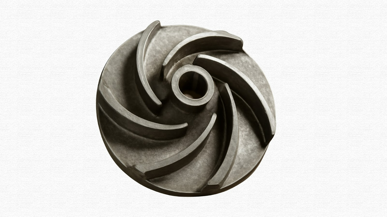
The impeller is the rotating workhorse that adds kinetic energy to the fluid. Key design factors include:
- Vane shape & curvature: Determines flow path, hydraulic efficiency, and the relationship between flow and head. More aggressive curvature yields a higher head but may increase wear.
- Open, semi‑open or enclosed shrouds: Open vanes help handle solids and slurries; enclosed impellers improve efficiency for clean fluids; semi‑open offers a balance.
- Specific speed & tip-speed: Higher specific speed designs deliver more flow at lower head; tip-speed must be managed to avoid cavitation and mechanical stress.
- Clearances & balancing: Impeller clearances (shroud to casing/wear ring) and dynamic balancing affect vibration, radial thrust, and wear. Poor balancing or excessive clearance reduces hydraulic performance and lifespan.
Volute or Diffuser Casing
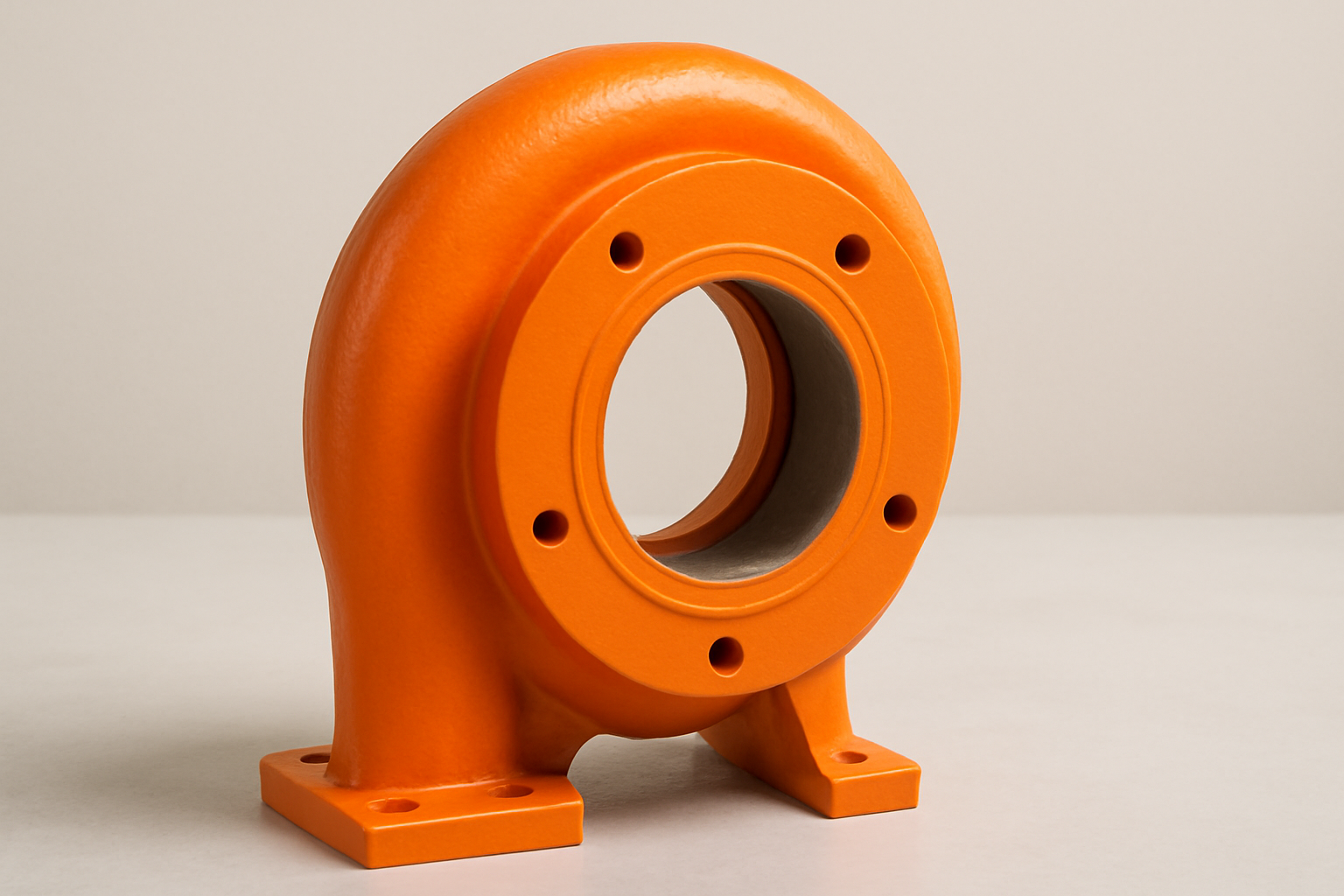
Casing turns the velocity from the impeller into usable pressure and channels the discharge flow:
- Volute casing: Spiral‑shaped casing that collects fluid from the impeller periphery and gradually expands cross‑section to slow velocity and convert it into pressure. The geometry of the volute influences radial forces, vibration, and efficiency.
- Diffuser casing: Uses fixed guide vanes or diffuser passages to decelerate flow more uniformly, often used in multi‑stage applications to reduce radial loads and improve efficiency.
- Split or double volute designs: Help balance radial thrust over wide flow ranges, stabilize axial loads, and reduce mechanical stress.
- Material choice: Metallic casings offer strength under pressure and abrasion; non‑metallic (polymers or lined designs) give enhanced corrosion resistance but require stronger structural support.
Shaft, Bearings, and Seals
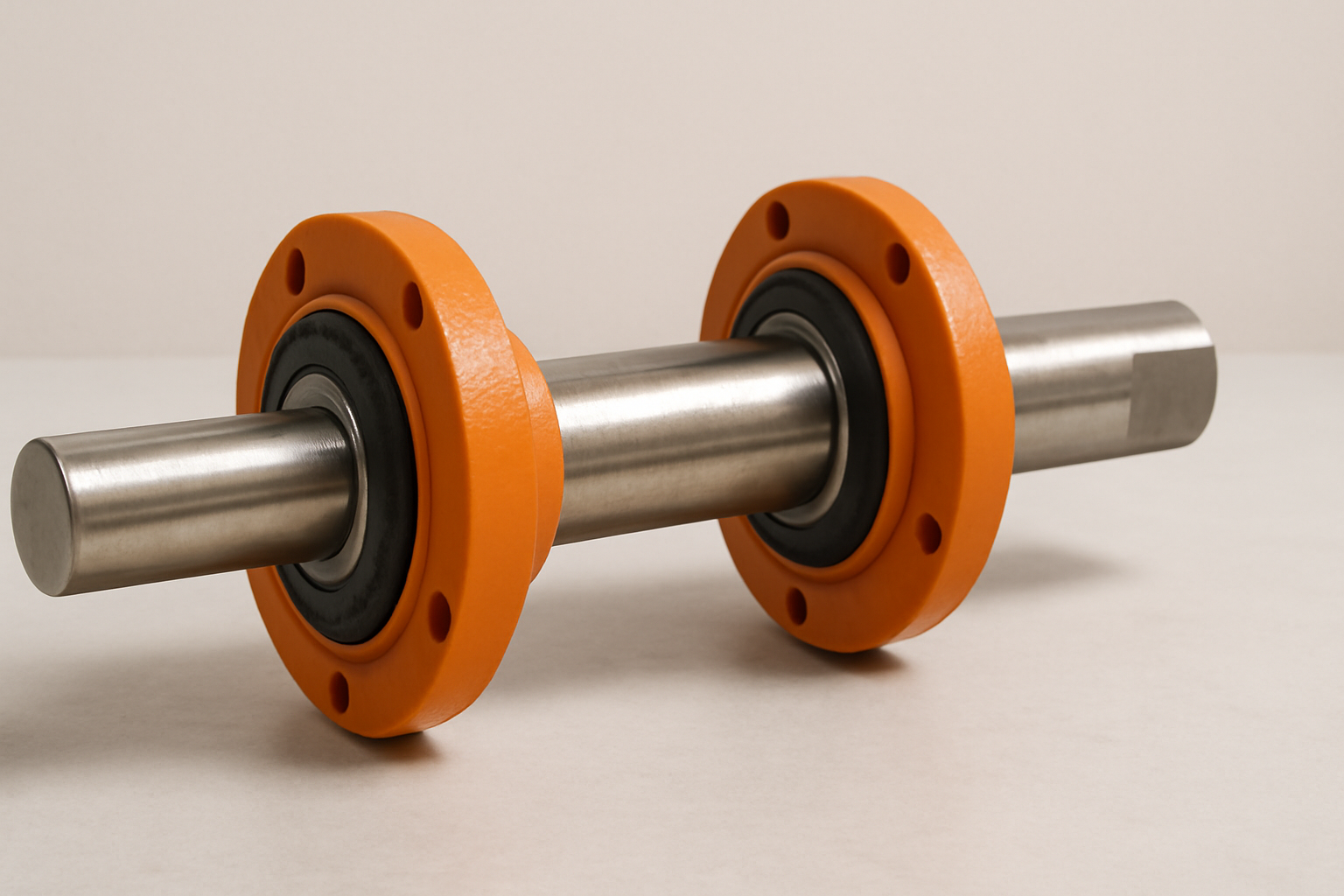
These mechanical-end components are critical to reliability, especially in harsh chemical, abrasive, or thermal environments.
- Shaft: Transmits torque; must be rigid, correctly aligned, and resistant to corrosion or deformation. Material selection (stainless steel, exotic alloys) is key, depending on fluid chemistry and temperature.
- Bearings: Support both radial and axial loads. Must be sized for expected forces (from impeller imbalance, radial thrust, axial thrust). Lubrication strategy and bearing type (rolling‑element, sleeve, or special bearings) affect MTBF significantly.
- Seals: Mechanical seals (single or double), cartridge/internal seal systems, or gland/packing options. The seal faces, secondary sealing elements (elastomers), and cooling/flushing arrangements need to be matched to the fluid’s chemical aggressiveness, temperature, and solids content to prevent leakage and premature failure.
Motor Coupling and Baseplate

While often undervalued, this “foundation” part of the system ensures that all the forces from the hydraulic side are transmitted without inducing excess vibration, misalignment, or fatigue.
- Coupling: Must accommodate misalignment, thermal expansion, and torque transmission. Flexible/spacer couplings allow easier maintenance and can protect seals and bearings.
- Baseplate: Provides structural rigidity. Must be flat‑machined, durable under thermal and mechanical stress, and properly aligned. Proper foundation and alignment between the motor and pump reduce vibration, extend bearing life, and maintain seal integrity.
For system integrators, the selection and configuration of impeller, casing, shaft, seal, and baseplate must align precisely with the process environment.
Chemitek’s engineering approach supports this by building pump assemblies that prioritize mechanical integrity, system fit, and long-term reliability, especially where harsh chemicals or extreme conditions are involved.
Performance Factors That Matter
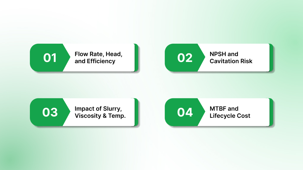
To ensure a rotodynamic pump performs reliably in industrial duty, several interlocking performance parameters must be managed. Ignoring even one can lead to inefficiencies, premature wear, or failure. Below are the chief factors to evaluate when selecting or engineering a pump system.
Flow Rate, Head, and Efficiency
Pump curves typically show how flow rate (Q) and head (H) relate. Efficiency tends to peak near the pump’s Best Efficiency Point (BEP). Operating too far above or below BEP causes higher losses, increased vibration, and lowered pump life.
Sizing a pump to meet process flow and head requirements under normal and peak load conditions is essential to avoid overloading the pump motor and to avoid recirculation or turbulence.
NPSH and Cavitation Risk
- Net Positive Suction Head Required (NPSHR) is a pump manufacturer’s characteristic: the minimum suction head required to avoid cavitation at a specific flow and speed.
- Net Positive Suction Head Available (NPSHA) is what your system offers, factoring in fluid vapor pressure, inlet piping losses, fluid temperature, etc. NPSHA must exceed NPSHR by a safety margin.
- ANSI/HI guidelines (e.g. 9.6.1) now provide revised NPSH margin recommendations, especially important in mixed or axial flow service where suction conditions are less forgiving.
Cavitation leads not only to audible noise and vibration, but literal damage erosion of impeller vanes and loss of hydraulic performance over time. Minimizing cavitation risk is a key factor in high‑duty applications.
Impact of Slurry, Viscosity, and Temperature
- Solids or suspended particles increase wear on impellers, seals, and casings. Pumps with semi‑open or open impellers and reinforced clearances are favored for ≥ moderate solids content.
- Viscosity changes the effective flow‐rate/head curve. Higher viscosity fluids reduce efficiency, increase required power, and may shift the BEP.
- Temperature affects fluid density, vapor pressure (which affects NPSHA), and material strength. Materials must be chosen to withstand both chemical and thermal stress. High temp also aggravates seal, bearing, and polymer degradation sooner.
MTBF and Lifecycle Cost
Mean Time Between Failures (MTBF) is heavily influenced by how closely the pump operates to the intended design parameters. Key influences:
- Pumps operating within ±10‑20% of BEP generally yield longer MTBF.
- Frequent seal failures, misalignment, vibration, or running at off‑design conditions multiply maintenance intervals and spare part costs.
- Lifecycle cost includes not just capital cost but energy consumption, maintenance, spare parts, and downtime. A modest improvement in efficiency (e.g. more efficient impeller or well‑matched casing) can yield significant cost savings over time.
Understanding these performance variables allows you to better align pump selection with your process needs, but knowing when to choose a rotodynamic pump over other types is just as critical. Let’s explore the applications where rotodynamic designs excel (and where they don’t).
When to Choose a Rotodynamic Pump
Rotodynamic pumps are not one-size-fits-all; they offer specific performance advantages and limitations that make them ideal for some applications and less suited for others. This section outlines when and why rotodynamic pumps are the right choice.
Ideal Applications by Industry
Rotodynamic pumps are widely used across industries where consistent flow, scalability, and compatibility with low- to medium-viscosity fluids are essential. Common applications include:
- Chemical processing: Transferring aggressive fluids at high volumes with moderate pressure requirements.
- Water and wastewater treatment: Handling large volumes with relatively clean fluids.
- HVAC and building systems: Circulating water or other heat-transfer fluids efficiently.
- Power generation: Cooling systems, condensate return, and boiler feed, where continuous flow is vital.
- Irrigation and agriculture: Large-scale water movement over varying distances.
Because rotodynamic pumps provide a stable flow and can be tuned to a wide performance range, they’re often the go-to choice for continuous or semi-continuous operations.
Limitations and What Not to Use It For
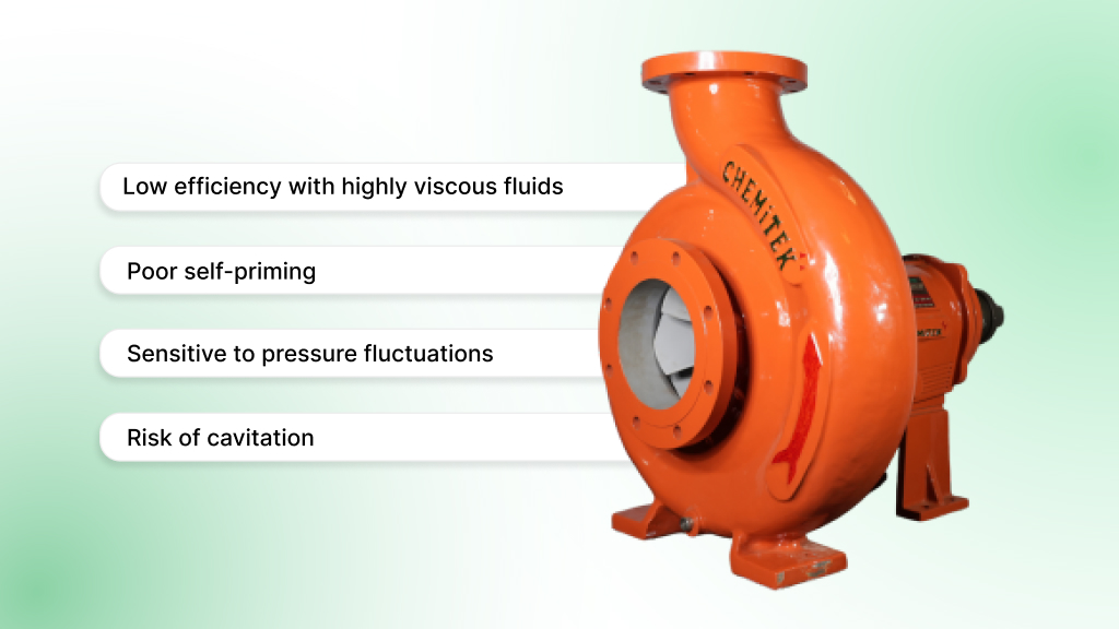
Despite their versatility, rotodynamic pumps are not ideal for every situation. Key limitations include:
- Low efficiency with highly viscous fluids: They struggle with thick liquids due to low shear force.
- Poor self-priming: Unlike positive displacement pumps, they typically require flooded suction or external priming systems.
- Sensitive to pressure fluctuations: Head and flow rate can drop off steeply with system changes.
- Risk of cavitation: In applications with inadequate NPSH or vapor pressure, cavitation can cause significant damage.
For dosing, metering, or applications requiring precise flow control regardless of system resistance, positive displacement pumps are often a better choice.
Metallic vs. Non-Metallic Options
Material compatibility plays a central role in pump longevity and safety. Rotodynamic pumps are available in both metallic and non-metallic constructions:
- Metallic (e.g., SS316, Hastelloy): Preferred for high-pressure or high-abrasion applications. More robust but heavier and susceptible to corrosion in certain chemistries.
- Non-metallic (e.g., PVDF, PP-H, FEP): Excellent chemical resistance and thermal insulation. Ideal for corrosive media, especially in chemical or pharma plants, though typically limited to ~25 kg/cm² pressure.
Material choice should align with the fluid’s chemical profile, operating temperature, and pressure conditions.
ANSI/ASME B73.1 and Compliance Factors
For many industrial environments, particularly in North America, compliance with ANSI/ASME B73.1 standards is essential. This standard ensures:
- Dimensional interchangeability across manufacturers
- Safety and reliability under corrosive or hazardous conditions
- Ease of maintenance and component replacement
Rotodynamic pumps built to this specification are especially valued in chemical and petrochemical sectors, where plant downtime and safety violations carry significant cost.
That’s why leading facilities turn to specialized manufacturers who understand not just the engineering principles of rotodynamic pumps, but how to adapt them to complex, high-risk environments.
Chemitek is one such partner, known for tailoring pump systems to meet the chemical, mechanical, and operational demands of modern process industries.
How Chemitek Engineers Rotodynamic Pumps for Real-World Conditions
Off-the-shelf rotodynamic pumps often fall short when exposed to harsh chemicals, high solids content, or extreme temperatures, common conditions in chemical, pharmaceutical, and process-intensive industries.
Chemitek addresses these challenges through application-specific engineering, ensuring that each pump is built not just to move fluid, but to survive and perform in its actual process environment.
Application-Matched Engineering
Rather than using standard configurations, Chemitek’s rotodynamic pumps are specified based on the chemical composition, temperature, pressure, and solids content of the fluid.
This allows for optimal selection of impeller type, seal system, and casing material, ensuring high efficiency and longer mean time between failures (MTBF) even in aggressive or variable conditions.
Non-Metallic Pumps for Harsh Chemicals
For corrosive media like acids, solvents, or halides, Chemitek offers non-metallic rotodynamic pumps constructed from PVDF, PFA, FEP, and PP-H. These polymers provide superior chemical resistance while being reinforced with metal armor for structural integrity.
This hybrid design enables operation at temperatures up to 210 °C and pressures up to 25 kg/cm².
Custom Sealing Systems for Zero-Leakage
Chemitek’s internal mechanical seal systems, including single and double configurations, are engineered to handle high-solid, high-temperature, or volatile chemical applications.
These modular cartridge-style seals minimize leak paths and simplify maintenance, making them ideal for safety-sensitive or continuous-process plants.
Modular Design for Quick Maintenance
Downtime is costly. Chemitek’s pumps use a back pull-out design and modular components, allowing impellers, seals, shafts, and bearings to be serviced without disturbing connected pipework. This design reduces repair time and simplifies spare part management, especially in multi-pump installations.
That level of maintainability isn’t a luxury; it’s essential for operations where uptime and safety are non-negotiable.
Whether you’re handling aggressive chemicals, abrasive slurries, or temperature-sensitive fluids, Chemitek delivers rotodynamic pump systems engineered for exact process compatibility.
Request a Component-Matched Pump for Your Process.
Conclusion: Precision in Pumping Starts with the Right Design
Rotodynamic pumps offer efficient, scalable flow for a wide range of industrial applications, but only when each component is aligned with the demands of the process. From impeller geometry to material selection and sealing systems, every detail impacts reliability, efficiency, and safety.
Understanding how rotodynamic principles translate into real-world performance is key to selecting the right pump. With tailored engineering, proven non-metallic options, and lifecycle-driven design, Chemitek helps plants reduce downtime, ensure compliance, and extend pump longevity in even the harshest environments.
FAQs About Rotodynamic Pumps
Q1: Are “rotodynamic” and “centrifugal” pumps the same thing?
A: Not exactly. A centrifugal pump is a subset of rotodynamic pumps, all centrifugal pumps fall under the rotodynamic category (along with mixed flow and axial flow types), but not all rotodynamic pumps are centrifugal. Rotodynamic refers broadly to pumps that use rotating impellers/rotors to impart kinetic energy to fluids, which is then converted to pressure.
Q2: What maintenance checks are essential for rotodynamic pumps to ensure long life?
A: Key maintenance items include: seal/gasket inspections for leakage, bearing lubrication and alignment, checking vibration/noise and temperature at bearings, verifying system flow vs. expected curve (especially Best Efficiency Point), and keeping spare parts (wear rings, sleeves, seals) available.
Preventive maintenance schedules should be tailored to fluid properties, load and duty cycle.
Q3: What causes cavitation in rotodynamic pumps, and how can it be prevented?
A: Cavitation occurs when local pressure falls below fluid vapor pressure, often due to insufficient Net Positive Suction Head Available (NPSHA), high fluid temperatures, vaporous fluid composition, or restrictive suction piping.
Prevention measures include ensuring adequate NPSHA, limiting the temperature, designing with proper casing/impeller geometry, avoiding oversized impellers, and avoiding prolonged operation far from the BEP.
Q4: How do slurry, viscosity, and solids content affect performance?
A: Slurry or solids increase wear in the impeller, casing, and seals, and reduce hydraulic efficiency. Higher viscosity fluids alter head vs. flow characteristics (often reducing flow and increasing required power).
Solids require open or semi-open impeller types, reinforced clearances, and robust materials for wetted parts.
Temperature also exacerbates these effects. (These are important for application‑matched component selection.) — (Chemitek’s NM style builds are engineered for such conditions.)
Q5: What spare parts are most critical to keep on hand for reducing downtime?
A: For rotodynamic pumps in continuous duty, spare parts that often limit uptime include: mechanical seals, wear rings or sacrificial rings, shaft sleeves, bearings, gaskets or O‑rings, and coupling parts. The fast availability of these reduces repair time significantly.
Latest posts

Understanding Rotodynamic and Centrifugal Pumps Differences
Ready to Upgrade Your Process Operations?